29" Full Suspension Mountain Bike
- Peter
- Jun 24, 2017
- 2 min read
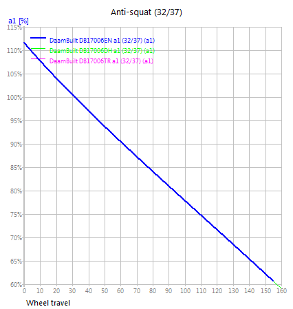
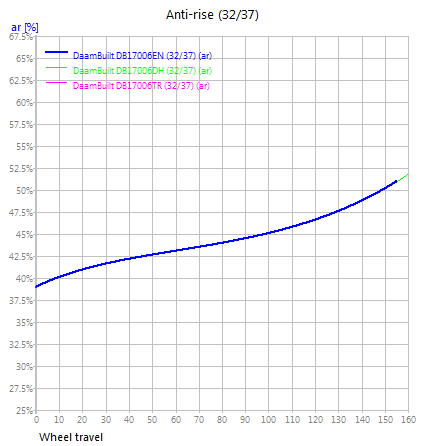
The rider had a favourite trail bike that he wanted to be a little longer, have more suspension travel and have more aggressive geometry. The rider wanted to achieve a neutral pedalling efficiency and ensure that the rear end was active under braking so that optimal traction would be achieved. Because of the desired criteria, it was decided to go with a Horst-Link 4 bar linkage design. Going this route I was able to fine tune the balance between braking and pedalling efficiency, while at the same time working with progressiveness values that matched the riders favourite trail bike.
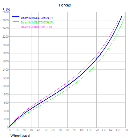
The rider also wanted to be able to use a coil shock and an air shock. The tricky part about designing a frame that can utilize both is matching the required progressiveness for each type of shock. Coil shocks are linear, and therefore a progressive linkage is required, where as an air shock is naturally progressive. To achieve this ability to use both shocks in this frame, multiple lower shock mounts were used.
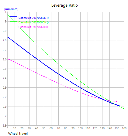
Mount 1: Trail - 150mm travel - 20% progressiveness (designed for air shock)
Mount 2: Enduro - 155mm travel - 35% progressiveness (designed for air or coil shock)
Mount 3: Downhill - 160mm travel - 48% progressiveness (designed for coil shock)
The above numbers were derived from a designed chain stay length of 440mm. Though because slider dropouts were used, the rider can go from 435mm all of the way up to 455mm.
The frame was designed around the use of 29x2.6" tires with the ability to go 27.5x3.0". Front travel was set at 160mm, which matched the rear travel from 150-160mm depending on the chosen lower shock mount.
Design geometry shown below:

Linkage layout:

Linkage layout at full compression:

Below are the linkage design graphs for each the leverage ratio, anti-squat (pedalling performance), anti-rise (braking performance) and forces. All three graphs show the different lower shock mount options for each progressivity. Anti-squat and anti-rise stay the same for each of the three settings, however leverage ratio and forces are different for each due to the changes in progressivity. (click on pictures to enlarge)
Once the bike was designed, it was time to get to work fabricating. The first step tackled was to work on the rear axle pivot.


Then the seat tube is cut and then aligned and welded together.

Front triangle top tube and down tubes are cut.

Main tubes are tacked and then welded together.

Working on the link plates, milling out of raw 7075-T6 Aluminum.

The design went through a Finite Element Analysis (FEA) to fine tune the balance between strength and weight.

Link plates installed with a dummy shock for assembly of the rear triangle. This picture shows the three lower shock mounts to achieve the different progressiveness level for the rider.

Chain stays were cut and welded. These needed to cooperate with 29x2.6" and 27.5x3.0" tires.

Rear triangle all welded up.

A close up of the link plates.

Ready for paint.

7075-T6 Aluminum anodized blue link plates back from the anodizer.

Back from paint with the glossy blue decals applied.

Linkage movement.


Handmade in Canada!


